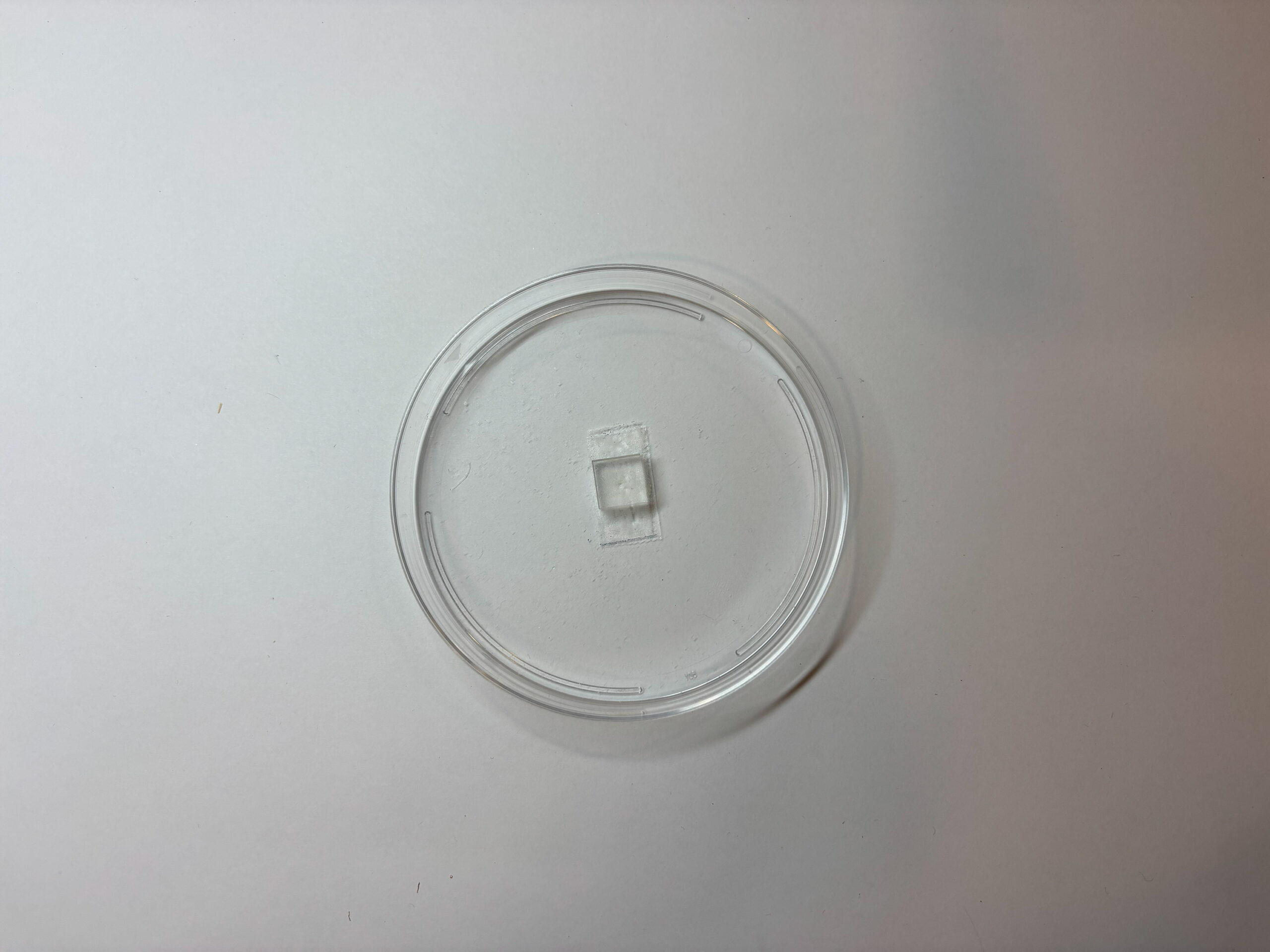
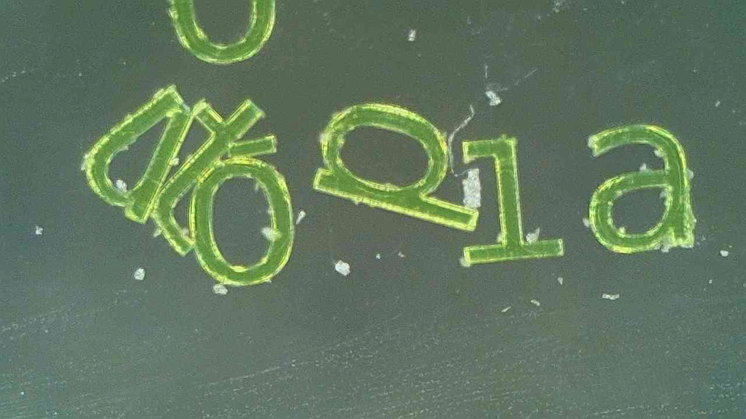
The Micropoetry (2025) project initially began as an exploration of the technology at the MIT.nano facilities, which include various equipment for fabricating and characterizing materials on the nanoscale. This resource was initially used to investigate the concept of the diffraction limit of the human eye, a physical threshold in optics where the human eye can longer resolve an image. Fabricating text on the nanoscale was the first step in this project, since text needs to be readable in order to gain meaning from it. While the main fabrication process at MIT.nano for fabricating on the nanoscale is a micro photolithographic process, it involved many steps with specialized machines that required specialized training. Instead, I settled on a 3D printing process that could print at the nanoscale. With the help of Ardalan SadeghiKivi, a staff member at MIT.nano, we made a print on an UpNano NanoOne 2-photon-based 3D printer, which uses a laser to cure resin at the nanoscale. The result was a 3D print of the words “technocrat utopia” printed in resin on top of a 10mm by 10mm by 5mm clear resin substrate base. This initial experiment produced the intended effect: the text is invisible to the unaided eye but was perfectly visible when viewed under a telescope. However, a glaring issue soon popped up: the print was too fragile to handle. With every attempt at handling the print, I had to be careful not to introduce too much movement, or accidentally swipe the surface where the text was printed. While I was able maintain the integrity of the print throughout successive attempts at characterization, the print deteriorated after each attempt, to the point that the print was completely destroyed.
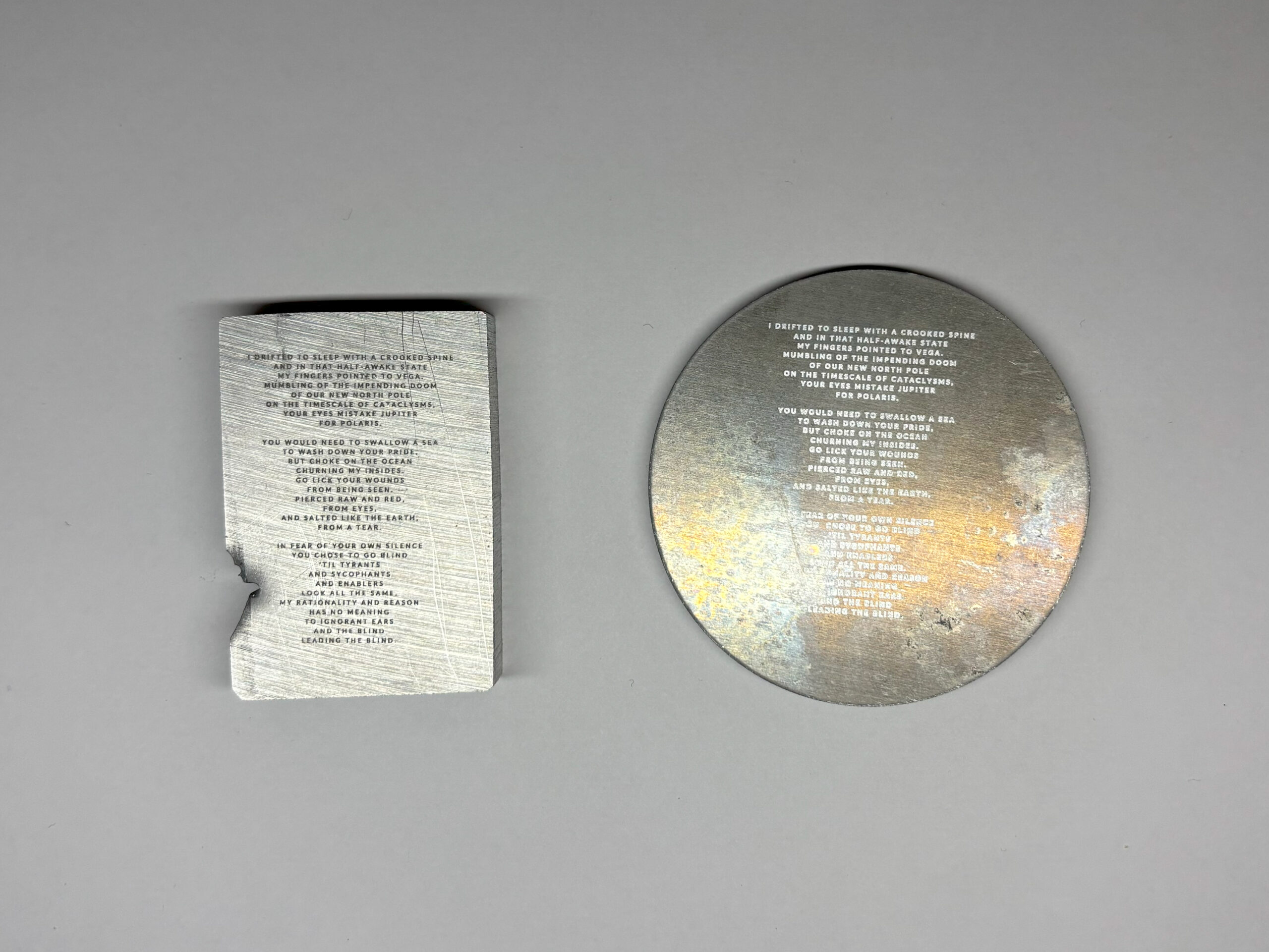
After this experience, alternative processes were pursued for fabricating text on the nanoscale that could withstand being handled on the human scale. The first alternative process that was attempted was laser micromachining with the xTool F1 Ultra laser engraver tool located in the Center for Bits and Atoms lab. The tool uses a laser to machine an image on substrate from top to bottom in successive lines. This required a heuristic calibration process to determine the smallest resolution the machine could produce, which depended on the power and speed of the laser, as well as the composition of the substrate. The results were two pieces of aluminum with the overall dimension of 50 millimeters with a text resolution of just under one millimeter per line of text.
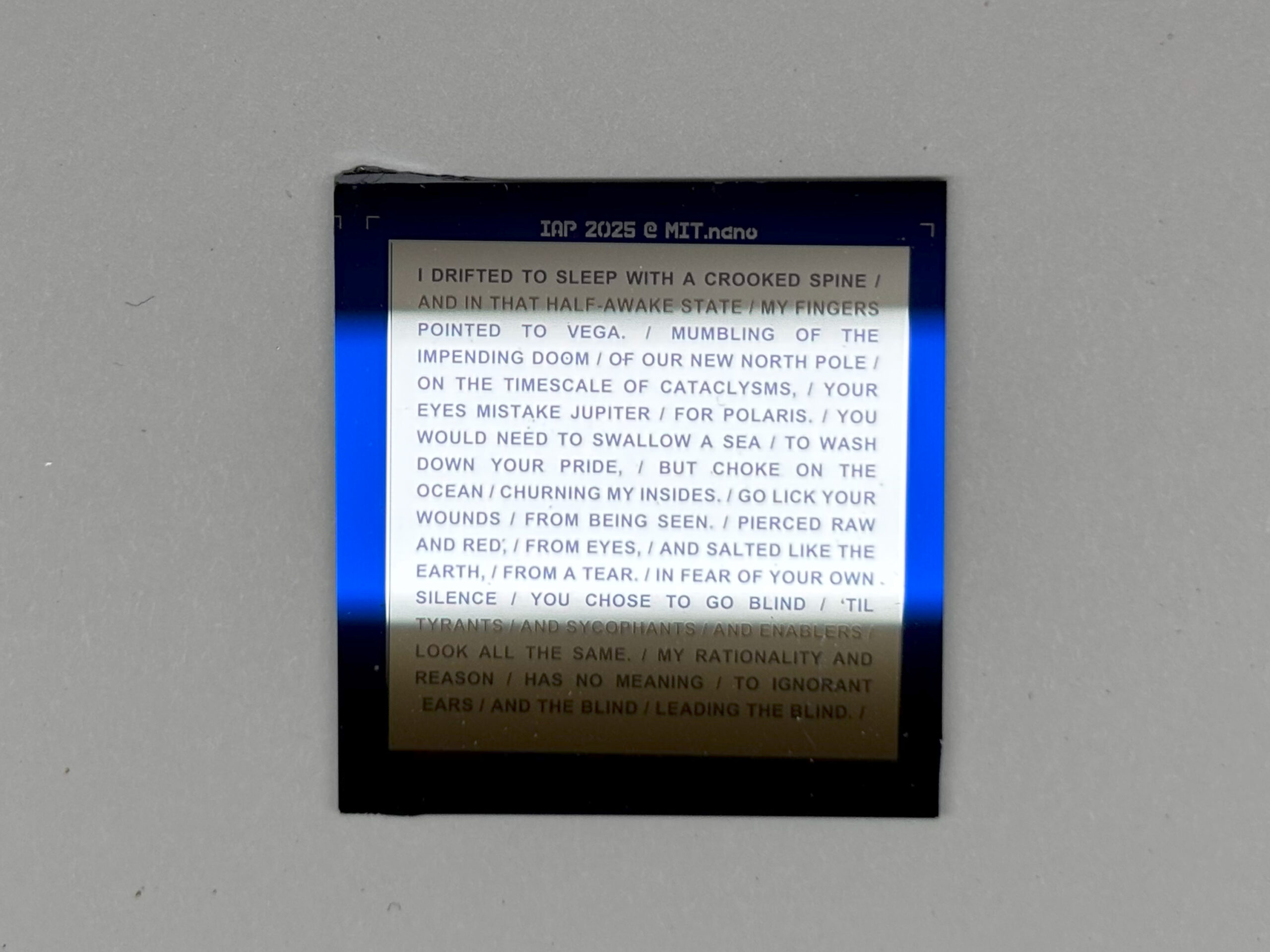
The second alternative process that was pursued was going back to MIT.nano and trying out the micro photolithography process. Unlike the laser micromachining, there was no calibration process to consistently test the smallest resolution the machine could produce; each test would require going through the entire photolithographic process over and over again. The result from this process was a 25 mm square silicon wafer with text the size of just under 1 millimeter per line of text.
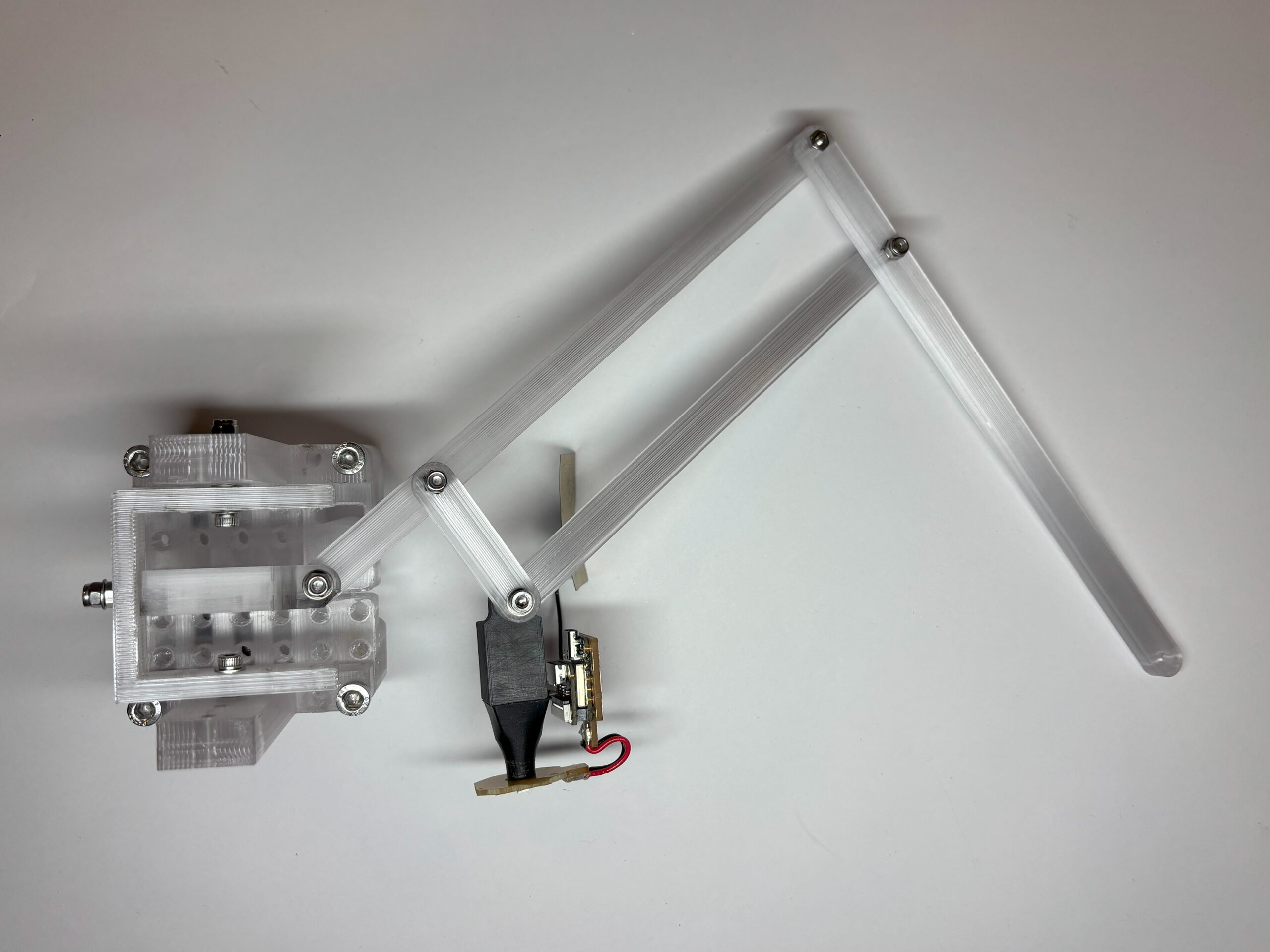
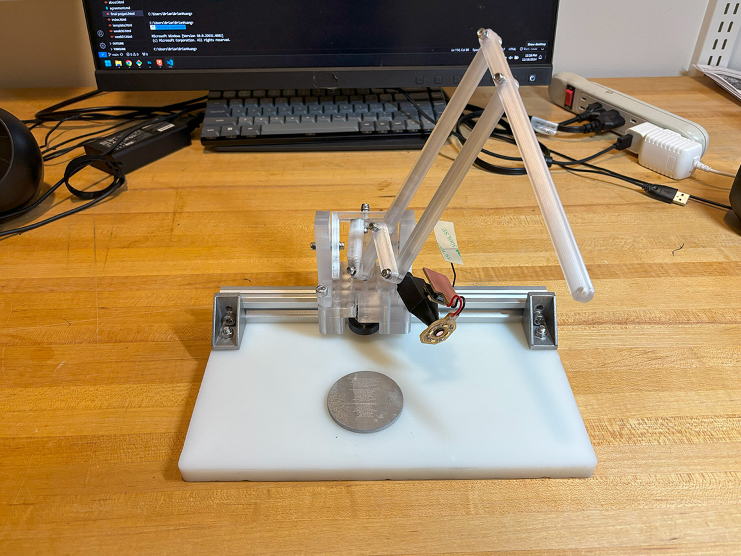
Previous installation of this project utilized a commercially available microscope, which stirred interest in building a custom apparatus for magnifying and viewing the laser engraved text and the photolithography text. The design process for this apparatus began with the basic form of the pantograph, a mechanical device composed of two hinged arms that intersect at a connecting pivot point on each opposing side of the arm. When connected, the two hinged arms form a parallelogram, which contracts and expands with movement. The longer external side of the arm is used as a handle for controlling the movement of the pantograph, while the shorter external side of the arm is used as an anchor point where the pantograph is connected to a stable base. The mechanism is able to telegraph linear movement: by moving the handle, the corner of the parallelogram that is colinear to the end the handle and the end of anchor point will mirror the movement, but on a proportionally smaller scale. The reverse is also possible: by using the corner of the parallelogram as the handle and the longer external side of the arm as the focus point of the end effect, the pantograph can be used to telegraph movement on a proportionally larger scale.
The anchor point of the pantograph is connected to the center of a universal joint, allowing for rotational movement in three dimensions. This universal joint is then placed on a linear motion carriage piece so that the apparatus could move perpendicular to the linear motion of the pantograph. An optical apparatus for performing live imaging made from a modified XIAO ESP32S3 camera module is placed on the colinear corner of the parallelogram. The camera module is modified by first removing the original lens, exposing access to the onboard camera sensor. A custom designed and 3D printed lens barrel is installed on top of the camera sensor, while the original camera lens is inverted and installed on the other side of the lens barrel, turning the entire apparatus into a 20x microscope objective. The entire mechanism is then installed atop a piece of HDPE that serves as a base, where a sample for characterization can be placed.